Robotic 3D Printing: How Industrial Robots Are Expanding the Limits of Additive Manufacturing
Robotics 3D Printing, RobotAdditive manufacturing has traditionally been associated with dedicated 3D printers built around a fixed machine architecture. These systems remain extremely effective for many applications, but their physical limitations become increasingly apparent as manufacturers move toward larger parts, more complex geometries, and unconventional materials.
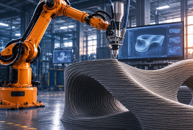
Robotic 3D printing offers a different approach. Instead of moving a print head within the constrained axes of a conventional printer, the manufacturing tool is mounted on an industrial robot. The robot can position the extruder, deposition head, laser, or other process tool from multiple directions, creating a much more flexible manufacturing platform.
This approach is particularly attractive for aerospace, automotive, construction, marine engineering, energy, tooling, and large-scale industrial production. It can make it possible to manufacture structures that would be difficult or impossible to produce using a conventional Cartesian 3D printer.
However, robotic additive manufacturing is not simply a larger version of desktop 3D printing. It requires different software, different process planning methods, and a more sophisticated approach to calibration, motion control, and production validation.
What Is Robotic 3D Printing?
Robotic 3D printing is an additive manufacturing process in which an industrial robotic arm controls the position and orientation of a deposition or processing tool.
The tool may be a conventional polymer extruder, a pellet-based thermoplastic extruder, a concrete deposition system, a metal wire arc additive manufacturing head, a laser, or another specialized manufacturing device.
The basic principle remains the same as in other additive manufacturing processes. Material is deposited or processed according to a digitally defined geometry, gradually creating the final part. The major difference is the kinematic system used to control the tool.
A conventional 3D printer generally operates within a fixed coordinate system. The print head moves along a limited number of linear axes, while the workpiece remains stationary or follows a relatively simple motion pattern.
An industrial robot, by contrast, typically provides six degrees of freedom. This allows the tool to move through complex three-dimensional trajectories while continuously changing its orientation.
Additional external axes can extend this capability even further. A robot may be mounted on a linear track, positioned above a rotary table, or combined with a positioner that rotates the workpiece during manufacturing.
The result is a flexible manufacturing cell rather than a traditional 3D printer.
How the Robotic Additive Manufacturing Workflow Works
Although robotic 3D printing involves more variables than conventional printing, the overall workflow follows a familiar digital manufacturing sequence.
1. Creating the digital model
The process begins with a CAD model or another digital representation of the desired part.
Depending on the application, the geometry may be designed specifically for additive manufacturing. This can include topology-optimized structures, lattice geometries, curved surfaces, hollow components, or large-scale architectural forms.
At this stage, engineers must consider not only the final shape of the part but also how it will be manufactured. The geometry, deposition direction, material behavior, and robot accessibility are closely connected.
2. Defining the deposition strategy
The digital model is then converted into a manufacturing strategy.
For a conventional printer, this usually means generating a sequence of planar layers. Robotic additive manufacturing offers considerably more freedom. The toolpath can follow curved surfaces, change orientation between layers, or use non-planar deposition strategies.
The software must determine factors such as:
- deposition paths;
- layer height;
- material flow rate;
- tool orientation;
- robot speed;
- acceleration and deceleration;
- collision avoidance;
- reachability;
- synchronization with external axes.
The resulting path is not simply a list of coordinates. It is a coordinated motion plan that must be compatible with the robot’s kinematics and the selected manufacturing process.
3. Converting the toolpath into robot motion
A CAM system generates a manufacturing path, but the robot does not execute generic G-code in the same way as a conventional 3D printer.
The planned trajectory must be translated into the native programming language and motion commands of the specific robot controller.
This is where post-processors and robotic simulation software become important. A post-processor converts the calculated path into instructions compatible with a particular robot model and controller.
The software must also account for the robot’s joint configuration. A single point in space can often be reached through multiple combinations of joint angles. Poor configuration choices can result in singularities, excessive joint movement, or inefficient trajectories.
4. Simulating the process
Before manufacturing begins, the entire operation should ideally be simulated in a virtual environment.
Simulation helps identify:
- collisions between the robot and the workpiece;
- collisions with fixtures or surrounding equipment;
- unreachable positions;
- singularities;
- excessive joint rotations;
- unexpected changes in tool orientation;
- problems caused by external axes.
For large and expensive components, simulation is particularly important because physical trial and error can be extremely costly.
5. Manufacturing the part
Once the trajectory has been verified, the robot executes the programmed motion.
Depending on the process, material may be deposited through an extruder, nozzle, wire, or other tool. The robot continuously moves the tool along the programmed path while the process parameters are controlled by the manufacturing system.
In advanced systems, sensors can be used to monitor temperature, material flow, bead geometry, deposition quality, or the position of the tool relative to the workpiece.
6. Inspection and post-processing
The printed component may require additional operations, including:
- machining;
- sanding;
- trimming;
- heat treatment;
- surface coating;
- painting;
- dimensional inspection.
One of the advantages of a robotic manufacturing cell is that the same robot can sometimes perform several of these operations by automatically changing tools.
A single robotic platform might therefore print a component, perform rough machining, switch to a finishing tool, and then carry out an inspection operation.
Why Six-Axis Robots Change Additive Manufacturing
The most important difference between robotic 3D printing and conventional additive manufacturing is not simply the size of the machine. It is the additional freedom of motion.
A conventional 3D printer typically builds a part layer by layer along a relatively fixed vertical direction. This works well for many geometries, but it also creates constraints.
Overhangs may require support structures. Curved surfaces may need to be approximated by many thin layers. Large parts may exceed the physical dimensions of the printer.
A robot can approach the same geometry from multiple directions.
Greater geometric freedom
The tool can be tilted and reoriented during the manufacturing process. This makes it possible to follow complex surfaces more naturally and to produce structures that would be difficult to build using strictly horizontal layers.
Non-planar toolpaths can also improve surface quality and reduce the visible stepping associated with conventional layer-by-layer manufacturing.
Fewer support structures
Support structures consume material and usually require additional post-processing.
By changing the orientation of the print head, a robot can often deposit material in a direction that provides better structural support for the next layer. This can reduce or eliminate supports in certain geometries.
The benefit is especially significant when working with expensive materials or very large structures.
However, support-free printing is not guaranteed. Material behavior, cooling, layer adhesion, and the specific deposition process still determine what geometries are physically possible.
Much larger working envelopes
The build volume of a conventional printer is determined primarily by the size of its frame.
A robotic system is not subject to the same limitation. A large robot can operate over a substantial workspace, and its reach can be extended with a linear rail or additional positioning system.
This makes robotic additive manufacturing particularly attractive for:
- large molds;
- aircraft components;
- marine structures;
- architectural elements;
- vehicle tooling;
- construction components;
- large-scale sculptures.
In some applications, the manufacturing system can be moved around the workpiece instead of placing the entire workpiece inside a machine.
Multiple materials and deposition technologies
A robot is essentially a flexible motion platform. The manufacturing tool can be changed depending on the material and process requirements.
Possible technologies include:
- thermoplastic extrusion;
- pellet extrusion;
- fiber-reinforced polymer deposition;
- concrete printing;
- metal wire arc additive manufacturing;
- laser-based deposition;
- ceramic and clay extrusion;
- composite material processing.
This flexibility allows the same robotic platform to be adapted to different manufacturing processes.
Robotic 3D Printing Is Not Limited to Plastic Filament
One of the most important differences between robotic additive manufacturing and consumer-oriented 3D printing is the range of material delivery systems available.
Polymer pellets
Instead of using filament, large robotic extruders can process plastic pellets.
Pellet extrusion can provide higher material throughput and lower material costs, making it suitable for large parts and industrial tooling.
Materials may include engineering thermoplastics and reinforced composites containing glass or carbon fibers.
Concrete and cementitious materials
Robotic systems are increasingly used for large-scale concrete deposition.
In construction, a robotic arm can deposit concrete according to a digital model, creating walls and architectural structures without conventional formwork.
This approach can reduce material waste and provide greater geometric freedom, although structural certification, reinforcement, curing, and construction regulations remain important engineering challenges.
Metal additive manufacturing
Robotic arms are also used for metal deposition, particularly in wire arc additive manufacturing.
A metal wire is fed into an arc-based deposition process, allowing large metal structures to be built relatively quickly.
Compared with powder-bed metal printing, robotic wire-based systems can offer a much larger working envelope and high deposition rates. They are particularly interesting for large components and repair applications.
The resulting parts often require machining to achieve final dimensional accuracy and surface finish.
Ceramics and other materials
Robotic extrusion systems can also process clay, ceramic materials, and other specialized compounds.
This is useful in architecture, artistic production, research, and experimental manufacturing where conventional printing systems may not provide the required scale or flexibility.
The Role of Software in Robotic 3D Printing
Hardware alone does not make a robotic 3D printer practical.
The software stack is one of the most important parts of the system.
A typical workflow may include:
- CAD modeling.
- Toolpath generation.
- Robotic kinematic planning.
- Collision detection.
- Simulation.
- Post-processing.
- Robot programming.
- Manufacturing execution.
- Monitoring and inspection.
The software must connect these stages into a reliable workflow.
CAM and robotic path planning
Traditional CAM software generates toolpaths for CNC machines. Robotic additive manufacturing requires additional information because the system must control both the position and orientation of the robot tool.
A path that is geometrically correct may still be impossible for a robot to execute.
For example, the robot may not be able to reach a section of the part without exceeding its joint limits. The tool may also rotate through an unstable configuration or collide with the workpiece.
Robotic CAM software must therefore combine manufacturing planning with robot kinematics.
Simulation and digital twins
Simulation allows engineers to test a manufacturing process before sending commands to physical equipment.
A digital model can represent:
- the robot;
- the print head;
- the workpiece;
- fixtures;
- external axes;
- the manufacturing environment.
This enables engineers to validate reachability and collision-free motion before production.
For large-scale additive manufacturing, this can save significant amounts of material and production time.
Post-processors
Each industrial robot manufacturer uses its own controller architecture and programming environment.
A post-processor converts the calculated robotic trajectory into instructions that the specific controller can understand.
This means that the same manufacturing strategy may require different output code for different robot models.
A strong software workflow should support a wide range of robot brands and provide tools for generating, simulating, and validating robot programs.
Where Robotic 3D Printing Creates the Most Value
Robotic additive manufacturing is not automatically better than a conventional 3D printer.
For small, simple parts, a dedicated printer is often cheaper, easier to operate, and more predictable.
Robotic systems become particularly attractive when the conventional approach creates significant limitations.
Large-scale manufacturing
The clearest use case is size.
If a component is too large to fit inside a conventional printer, a robot may provide a practical alternative.
The robot can manufacture the part in a large open workspace or build it directly on a fixed structure.
Complex geometry
Robotic motion can simplify the manufacturing of parts with:
- curved surfaces;
- deep undercuts;
- complex orientations;
- large overhangs;
- irregular geometries.
The ability to continuously change tool orientation can reduce the need to divide a component into multiple smaller parts.
Tooling and molds
Large molds and tooling are attractive applications because they often require significant amounts of material and can take a long time to manufacture using conventional methods.
A robotic extruder can produce a near-net-shape mold relatively quickly. The surface can then be machined to achieve the required accuracy and finish.
This approach can significantly reduce lead times compared with traditional tooling methods.
Construction
Robotic additive manufacturing is also being explored for buildings, architectural structures, and large construction components.
The ability to deposit material directly from a digital model can enable customized geometries and reduce the need for traditional formwork.
However, construction applications require careful consideration of structural performance, building codes, reinforcement, weather conditions, and process reliability.
Aerospace and automotive production
In aerospace and automotive manufacturing, robotic additive systems can be used for large components, prototypes, molds, tooling, and repair operations.
The technology is particularly useful when a part is too large for conventional additive manufacturing but still benefits from digital production.
Art and experimental design
The flexibility of robotic motion makes the technology attractive for large-scale sculptures, architectural installations, and experimental structures.
Artists and designers can use the robot as a programmable motion platform rather than simply as a conventional printer.
Important Limitations and Engineering Challenges
Despite its advantages, robotic 3D printing introduces challenges that should not be underestimated.
Lower absolute accuracy than dedicated machines
Industrial robots are highly repeatable, but their absolute positional accuracy is generally lower than that of specialized CNC machines.
This matters when the printed part must meet tight dimensional tolerances.
In many applications, the solution is to combine robotic deposition with subsequent CNC machining.
The robot creates the near-net shape, while a machining operation produces the final precision surfaces.
Kinematic complexity
A robot can reach the same position through different joint configurations.
Poor path planning can result in:
- sudden orientation changes;
- excessive joint movement;
- singularities;
- unstable motion;
- unnecessary cycle time.
These issues must be detected during simulation and corrected before production.
Process consistency
The quality of an additive manufacturing process depends on more than the path itself.
Material temperature, deposition rate, cooling conditions, layer adhesion, and robot speed all affect the final result.
A technically correct robot trajectory can still produce a defective component if process parameters are not properly controlled.
Calibration
The relationship between the robot, the tool, the workpiece, and the digital model must be accurately calibrated.
Errors in tool-center-point calibration or workpiece positioning can cause the actual deposition path to differ from the planned path.
Calibration becomes increasingly important as part size and dimensional requirements increase.
Software complexity
A robotic additive manufacturing cell typically requires more software integration than a conventional desktop printer.
Engineers may need to manage CAD, CAM, robot programming, simulation, process control, and inspection systems.
This increases the importance of software interoperability and a well-defined manufacturing workflow.
Robotic 3D Printing Versus Conventional 3D Printing
The choice between a conventional printer and a robotic system depends primarily on the application.
A conventional 3D printer is often the better choice when:
- parts are relatively small;
- high dimensional accuracy is required directly from the printer;
- the manufacturing process is standardized;
- the geometry is compatible with fixed-axis printing;
- the production environment requires simple operation.
A robotic system becomes more attractive when:
- the part is very large;
- the geometry requires multiple tool orientations;
- support structures would be extensive;
- multiple materials or tools are needed;
- the same platform must perform printing and other manufacturing operations;
- the process requires an unusually large or flexible working envelope.
The key question is not whether robots are more advanced than conventional 3D printers. The more useful question is whether the additional flexibility solves a real manufacturing problem.
A Robotic Cell Can Become More Than a 3D Printer
One of the strongest arguments for robotic additive manufacturing is that the robot can perform several operations.
A single cell may be equipped with an automatic tool changer and use different tools for:
- additive deposition;
- milling;
- drilling;
- trimming;
- sanding;
- inspection.
This creates a hybrid manufacturing system.
For example, a robot could deposit a large polymer structure, switch to a milling spindle, machine critical surfaces, and then use a measurement probe to inspect the finished component.
Such an approach can reduce the number of separate machines and simplify the movement of large workpieces between production stages.
How to Evaluate Whether Robotic 3D Printing Is Right for Your Business
Before investing in a robotic additive manufacturing system, manufacturers should evaluate several factors.
Part size
If your components consistently exceed the build volume of conventional printers, robotics may provide a clear advantage.
Geometry
Analyze whether your parts require complex orientations or large support structures. If the geometry can be manufactured efficiently using a fixed-axis printer, a robotic system may not provide enough additional value.
Material requirements
The selected material must be compatible with a suitable deposition process.
Consider:
- material cost;
- throughput;
- temperature requirements;
- mechanical properties;
- shrinkage;
- adhesion;
- post-processing requirements.
Required accuracy
Robotic additive manufacturing is often best suited to near-net-shape production followed by machining.
If the final part requires very tight tolerances, the complete production process should include an appropriate finishing operation.
Production volume
For very high volumes of identical small parts, specialized additive or conventional manufacturing equipment may be more efficient.
Robotic printing becomes particularly attractive for large parts, prototypes, customized products, tooling, and low-to-medium production volumes.
Available engineering expertise
A robotic additive manufacturing cell requires knowledge of:
- robot programming;
- CAD/CAM;
- process engineering;
- material science;
- automation;
- industrial safety.
Companies should consider whether these capabilities already exist internally or whether additional training and integration support will be required.
The Future of Robotic Additive Manufacturing
The development of robotic 3D printing is closely connected to several broader trends in manufacturing.
One is the increasing use of digital twins and simulation. Better virtual models make it possible to optimize robotic paths before production begins.
Another is the growth of sensor-based process monitoring. Cameras, thermal sensors, force sensors, and other measurement systems can provide feedback during manufacturing and help detect defects earlier.
Artificial intelligence may also play a role in optimizing toolpaths, adjusting process parameters, predicting defects, and improving material deposition.
At the same time, hybrid manufacturing is likely to become increasingly important. Instead of treating additive manufacturing and machining as separate processes, manufacturers can combine them within a single automated production cell.
Conclusion
Robotic 3D printing expands additive manufacturing beyond the physical limitations of conventional fixed-axis machines.
By combining industrial robot kinematics with digital fabrication, manufacturers can produce larger structures, access more complex geometries, reduce support requirements, work with a broader range of materials, and integrate multiple manufacturing operations into a single flexible cell.
The technology is not a universal replacement for conventional 3D printers. For small and standardized parts, dedicated machines often remain the most practical solution.
The strongest business case for robotic additive manufacturing appears when conventional equipment reaches its limits. Very large components, complex geometries, specialized materials, custom tooling, and hybrid manufacturing workflows are all areas where the flexibility of a robotic system can create measurable value.
The most important decision is therefore not simply whether to buy a robot and attach a 3D printing head to it. Successful implementation requires a complete manufacturing workflow that combines suitable materials, process engineering, robotic motion planning, simulation, calibration, and quality control.
When those elements are properly integrated, a robotic arm becomes far more than a large 3D printer. It becomes a programmable manufacturing platform capable of adapting to a wide range of production challenges.